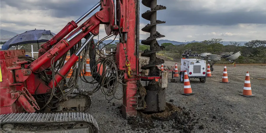
Tulsa’s development history, from the oil boom of the early 1900s to its modern expansion along the Arkansas River, has left a patchwork of soil conditions that challenge foundation engineering. Much of the metropolitan area sits on Pleistocene-age terrace deposits and alluvial floodplain silts that can exhibit low bearing capacity and high compressibility. For projects where shallow foundations are insufficient and rigid deep foundations prove uneconomical, ground improvement using aggregate piers becomes the logical option. Stone column design in Tulsa requires a careful evaluation of the in-situ undrained shear strength and a clear understanding of the lateral confinement provided by the surrounding matrix, since the method relies on bulging capacity rather than end-bearing. Before mobilizing a vibroflot crew, we integrate data from a CPT test to develop a continuous profile of tip resistance and sleeve friction, which allows us to predict column behavior across interbedded sand and clay layers common in the Verdigris River watershed.
Effective stone column design converts loose, liquefiable alluvium into a composite mass capable of supporting 4,000 to 6,000 psf bearing pressure with settlement reduced by nearly 60 percent.
Methodology and scope
We also validate the treatment zone with plate load tests conducted in accordance with ASTM D1194, ensuring the composite ground stiffness meets the project’s differential settlement tolerance, particularly critical for tilt-sensitive structures like grain silos near the Port of Catoosa.
Local considerations
With a population exceeding 413,000 within city limits and a metropolitan area nearing one million, Tulsa’s building stock faces a moderate seismic hazard amplified by the site class E soils prevalent in the Arkansas River corridor. The 2011 Prague earthquake sequence, though centered 50 miles away, produced peak ground accelerations that exceeded 0.10g in parts of Tulsa County, reminding engineers that intraplate seismicity demands attention. Stone column design in Tulsa must therefore address liquefaction potential as much as static settlement, particularly in the saturated fine sands and low-plasticity silts mapped as liquefaction susceptibility category L4 by the Oklahoma Geological Survey. A factor of safety against liquefaction below 1.1 for a benchmark magnitude 6.0 event often triggers the need for drainage and densification functions that stone columns provide. Ignoring this dual settlement-seismic requirement can lead to differential movements exceeding 2 inches, causing structural distress in tilt-up concrete warehouses and mid-rise steel frames alike.
Applicable standards
ASTM D1586-18 (Standard Test Method for SPT), ASTM D2487-17 (Unified Soil Classification System), FHWA-NHI-16-027 (Ground Improvement Methods), IBC 2021 Chapter 18 (Soils and Foundations), ASCE 7-22 Minimum Design Loads
Associated technical services
Stone Column Feasibility & Design Report
We prepare a comprehensive design package that includes the unit cell analysis, calculation of the improvement factor, determination of critical column length, and specification of the stone gradation and compaction criteria. The report references site-specific SPT and CPT data and provides a gridded layout with settlement predictions under the proposed structural loads.
Post-Installation Modulus Verification
Using zone load tests or large-diameter plate load tests per ASTM D1194, we confirm that the composite shear modulus of the treated ground meets the design assumptions. The program includes statistical analysis of at least one test per 5,000 square feet of treatment area, with modulus degradation curves plotted for the design earthquake scenario.
Typical parameters
Frequently asked questions
What soil conditions in Tulsa are most suitable for stone columns?
Stone columns are most effective in loose sands, silty sands, and soft to medium-stiff clays with an undrained shear strength above 15 to 20 kPa. Much of the alluvial plain near the Arkansas River falls into this category. They are not recommended for peat, highly organic soils, or very sensitive clays where remolding during vibro-installation can cause excessive strength loss.
How do you verify that the stone columns meet the design specification?
Verification relies on three primary methods: real-time monitoring of vibroflot amperage and lift thickness during installation, post-treatment cone penetration tests (CPT) between columns to measure the increase in tip resistance, and zone load tests or individual plate load tests. The acceptance criteria are typically a minimum composite modulus and a maximum allowable settlement under 150% of the design load.
What is the typical cost range for a stone column design package in Tulsa?
For a standard commercial or light industrial project in Tulsa, the geotechnical design package—including feasibility analysis, unit cell modeling, settlement calculations, and load test specifications—generally ranges from US$1,470 to US$4,840 depending on the treatment area and the complexity of the subsurface profile.
How does stone column design address liquefaction in Tulsa?
The columns serve a dual purpose: they densify the surrounding granular soil during vibro-compaction and act as vertical drains that allow rapid dissipation of excess pore water pressure during cyclic loading. The design calculates the residual excess pore pressure ratio and the time required for drainage, ensuring that liquefaction is mitigated within the critical first 20 to 30 seconds of strong shaking.
What information do you need to begin the stone column design process?
We require a geotechnical investigation report with SPT N-values or CPT tip resistance and sleeve friction data to a depth of at least two times the column length. Groundwater level data, grain size distribution curves, and Atterberg limits are essential for assessing liquefaction and drainage. The structural loading and allowable settlement criteria from the project engineer also form the basis of the unit cell analysis.